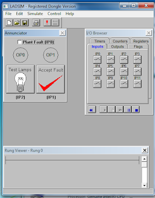
LADSIM is a fully
functional ladder logic design and PLC simulation software program that
incorporates the functions used in PLC ladder programming. LADSIM uses the PC
as a virtual PLC.
Figure 1. LADSIM Interface
There are three main screen of LADSIM:
1.
The Ladder Logic Diagram Window
This
is where the ladder code is displayed. Each time you add or edit a rung, the
result will be shown here.
Rung is serves as conditioning
for command input and output logic.
2.
The Controls box.
This
contains the ladder symbols that are used to create the ladder diagram. See
below for further details.
3.
The toolbar
This
includes the standard buttons of LADSIM and allows you to start a new diagram,
open an existing file, print, save and comment your ladder diagram.
You aso can apply your ladder code to run simulations in LADSIM. These simulations are:
1.
Traffic Light
Code must be written to control the
sequence of operation of the lights. A typical sequence could be : RED 'ON'
immediately After 2 seconds YELLOW 'ON' After 3 seconds GREEN 'ON' only After 5 seconds YELLOW 'ON' only After 1 second Restart Sequence. The task would be to code this sequence
in ladder logic and operate the lights accordingly.
2.
The Annunciator
In industry, plant conditions need
to be monitored and, if there are problems, a way of indicating these problems.
An indicator system of this type is called an annunciator. A typical alarm
system uses the following sequence to indicate a plant alarm condition to an
operator. System healthy - no indication. System in alarm - a flashing light
and audible alarm.
The annunciator in LADSIM must be programmed to allow
the correct operation.
3.
The Car Park
The diagram shows the layout of a
simple car park. It has an entry barrier and an exit barrier. The car park
itself has six spaces and a series of displays to indicate whether it is full,
has spaces or is empty, with a numerical indicator to determine the exact
amount.
Ladder code needs to be written that will allow cars
into the car park when it is empty or has spaces and to exit the car park
through the correct barrier. Ladder code must also be written to control the
display boxes in the centre of the screen.
4.
The Lift (Elevator)
A program is required that will drive
the lift from one floor to the other on a signal from the call button. Safety
is essential and we must be careful not to have anything obstructing the
operation of the doors.
5.
The Drinks Machine
When a coin is placed into the slot,
the user should be able to select his or her favourite drink or reject the
coin. It is important to ensure that
the coin cannot be rejected once a drink has been selected or that selecting a
drink disables all of the other drink buttons.
6. The Packing Line
The packing line carries boxes of
different sizes which need to be separated into their relevant sizes.
Which direction the boxes go is decided by using the
input sensors IP0 and IP1. If a box is short, only one of the inputs is energised
at any one time. If it is a long box, then both inputs will be energised. These results can then be used to activate
the correct solenoid and the direction of rotation of the circular plate.
7.
The Bottling Plant
The graphic is an overview of a
simplified bottling plant with a filling station and packing area. Bottles are
fed along the first conveyor, conveyor 1, into the filling station. The bottles
must be stopped and filled with milk and then have a cap placed on them. Once
accomplished, they go onto conveyor 2 where the cap is screwed on tight. They
are finally stacked in the stacker area where they are pushed onto conveyor 3.
References:
Imelia Rizki Lestari


.jpg)
0 comments:
Post a Comment